Što je enkoder?
Tijekom rada motora, praćenje parametara u stvarnom vremenu kao što su struja, brzina vrtnje i relativni položaj obodnog smjera rotirajućeg vratila određuje statusmotorkaroserije i opreme koja se vuče, te nadalje, upravljanje motorom i radnim uvjetima opreme u stvarnom vremenu, čime se ostvaruje servo upravljanje, regulacija brzine i mnoge druge specifične funkcije.
Ovdje primjena enkodera kao prednjeg mjernog elementa ne samo da uvelike pojednostavljuje mjerni sustav, već ga čini i preciznim, pouzdanim i snažnim.
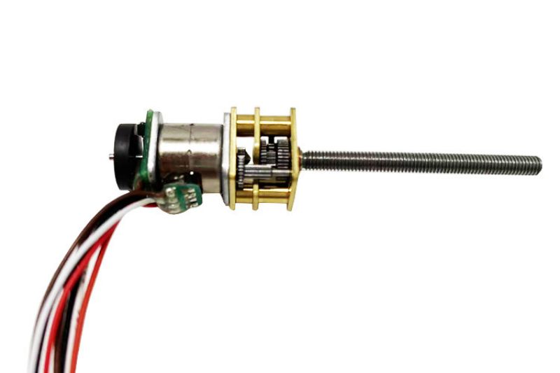
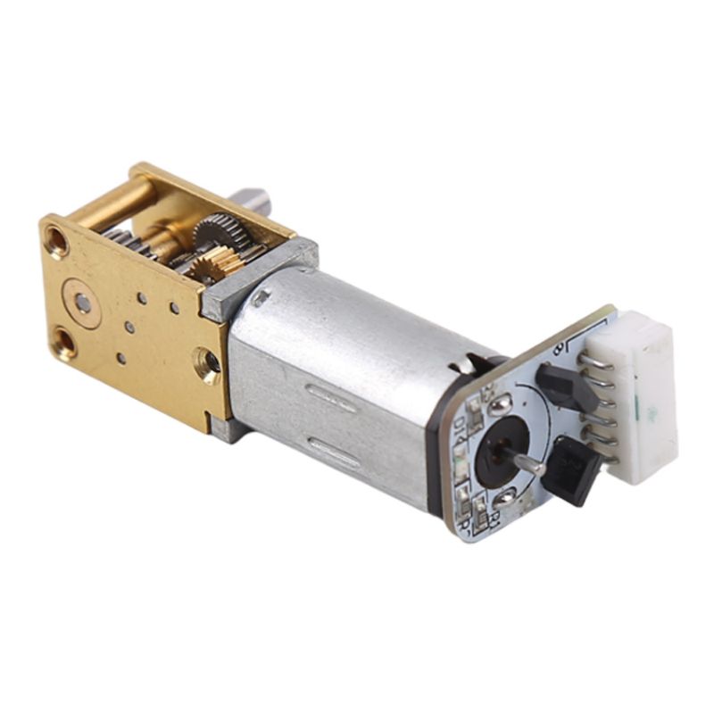
Enkoder je rotacijski senzor koji pretvara položaj i pomak rotirajućih dijelova u niz digitalnih impulsnih signala koje upravljački sustav prikuplja i obrađuje kako bi izdao niz naredbi za podešavanje i promjenu radnog stanja opreme. Ako se enkoder kombinira s zupčastom šipkom ili vijkom, može se koristiti i za mjerenje fizičkih veličina položaja i pomaka linearnih pokretnih dijelova.
Osnovna klasifikacija enkodera
Enkoder je mehanička i elektronička bliska kombinacija preciznih mjernih uređaja, signala ili podataka za kodiranje, pretvorbu, za komunikaciju, prijenos i pohranu signalnih podataka.
Enkoder je precizni mjerni uređaj koji kombinira mehaničke i elektroničke komponente za kodiranje, pretvaranje, komunikaciju, prijenos i pohranu signala i podataka. Prema različitim karakteristikama, klasifikacija enkodera je sljedeća: kodni disk i kodna skala: linearni pomak u električne signale koji se nazivaju kodni skalni enkoder, kutni pomak u telekomunikacije za kodni disk, - inkrementalni enkoder: za određivanje položaja, kuta i broja krugova itd., za određivanje broja impulsa po okretu kako bi se definirala brzina odvojenog pomicanja. - Apsolutni enkoder: Pruža informacije kao što su položaj, kut i broj okretaja u kutnim koracima, pri čemu se svakom kutnom koraku dodjeljuje jedinstveni kod.
-Hibridni apsolutni enkoderi: Hibridni apsolutni enkoderi daju dva seta informacija: jedan set informacija koristi za detekciju položaja magnetskih polova, s funkcijom apsolutnih informacija; drugi set je potpuno isti kao i izlazne informacije inkrementalnih enkodera.
Često korišteni enkoderi zamotori
Inkrementalni enkoder
Izravno korištenje principa fotoelektrične pretvorbe za izlaz tri seta pravokutnih valnih impulsa A, B i Z. A i B dva seta impulsa s faznom razlikom od 90° mogu lako odrediti smjer vrtnje; Z-faza svaki okret daje impuls, koristi se za pozicioniranje referentne točke. Prednosti: jednostavan princip konstrukcije, prosječni mehanički vijek trajanja od desetaka tisuća sati ili više, jaka sposobnost sprječavanja smetnji, visoka pouzdanost, pogodno za prijenos na velike udaljenosti. Nedostaci: ne može iznijeti apsolutne informacije o položaju rotacije osovine.
Apsolutni enkoderi
Izravni izlaz digitalnog senzora, kružni kodni disk senzora duž radijalnog smjera brojnih koncentričnih kodnih kanala, svaki kanal po sektorima prozirnim za svjetlost i sektorima nepropusnim za svjetlost između sastava broja susjednih sektora kodnih kanala dvostruki je odnos između broja kodnih kanala na kodnom disku koji je broj binarnih znamenki na broju kodnih kanala koji je broj bitova njegovog kodnog diska, na strani kodnog diska izvora svjetlosti, na drugoj strani odgovarajućeg kodnog kanala nalazi se element osjetljiv na svjetlost; kada se kodni disk nalazi u različitim položajima, element osjetljiv na svjetlost pretvara odgovarajuću razinu signala u binarni broj prema svjetlu ili ne. Kada se kodni disk nalazi u različitim položajima, svaki fotosenzibilni element pretvara odgovarajuću razinu signala prema tome je li osvijetljen ili ne, u binarni broj.
Ova vrsta enkodera karakterizira se činjenicom da ne zahtijeva brojač i fiksni digitalni kod koji odgovara položaju može se očitati na bilo kojem položaju rotirajućeg vratila. Očito je da što je više kodnih kanala, to je veća rezolucija. Za enkoder s N-bitnom binarnom rezolucijom, kodni disk mora imati N kanala barkoda. Trenutno postoje proizvodi s 16-bitnim apsolutnim enkoderom.
Princip rada enkodera
Sredinom s osovinom fotoelektrične kodne ploče, koja ima prsten kroz tamne linije, nalaze se fotoelektrični odašiljač i prijemnik za očitavanje, kako bi se dobila četiri seta sinusnih valnih signala kombiniranih u A, B, C, D, svaki sinusni val s faznom razlikom od 90 stupnjeva (u odnosu na obodni val za 360 stupnjeva), inverzni C, D signali, superponirani na dvofazni A, B, koji se može pojačati radi stabilizacije signala; a drugi svaki okret za izlaz Z-faznog impulsa u ime referentnog položaja nultog položaja.
Budući da se fazna razlika A i B od 90 stupnjeva može usporediti s fazom A sprijeda ili fazom B sprijeda, kako bi se razaznalo pozitivno i obrnuto okretanje enkodera, putem nultog impulsa može se dobiti nulti referentni položaj enkodera.
Materijal enkodera je staklo, metal i plastika. Stakleni disk se taloži na staklu na vrlo tankoj graviranoj liniji. Njegova toplinska stabilnost je dobra i visoka preciznost. Metalni disk može izravno proći, a ne proći graviranu liniju. Nije krhak, ali zbog određene debljine metala preciznost je ograničena, a toplinska stabilnost je za red veličine lošija od staklenog diska. Plastični disk je ekonomičan, cijena mu je niska, ali točnost, toplinska stabilnost i vijek trajanja su lošiji. Plastični diskovi su ekonomični, ali točnost, toplinska stabilnost i vijek trajanja su lošiji.
Rezolucija - enkoder koji određuje koliko kroz ili tamnih linija po rotaciji od 360 stupnjeva naziva se rezolucija, također poznata kao rezolucija indeksa ili izravno nazvana koliko linija, općenito 5 ~ 10 000 linija po okretaju indeksa.
Principi mjerenja položaja i upravljanja povratnom vezom
Enkoderi zauzimaju izuzetno važnu poziciju u dizalima, alatnim strojevima, obradi materijala, sustavima povratne veze motora i opremi za mjerenje i upravljanje. Enkoderi koriste optičke rešetke i izvore infracrvene svjetlosti za pretvaranje optičkih signala u TTL (HTL) električne signale putem prijemnika, koji vizualno odražava kut rotacije i položaj motora analizirajući frekvenciju TTL razine i broj visokih razina.
Budući da se kut i položaj mogu točno izmjeriti, moguće je formirati sustav upravljanja zatvorene petlje s enkoderom i pretvaračem kako bi upravljanje bilo još preciznije, zbog čega se dizala, alatni strojevi itd. mogu koristiti tako precizno.
Sažetak
Ukratko, razumijemo da se enkoder dijeli na inkrementalni i apsolutni, a postoje i drugi signali, poput optičkih signala, te električni signali koji se mogu analizirati i kontrolirati. A živimo u uobičajenom liftu, alatni strojevi temelje se samo na preciznoj regulaciji motora, putem povratne informacije električnog signala u zatvorenoj petlji upravljanja, enkoder s frekvencijskim pretvaračem također je neophodan za postizanje precizne kontrole.
Vrijeme objave: 23. veljače 2024.


